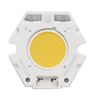
Description
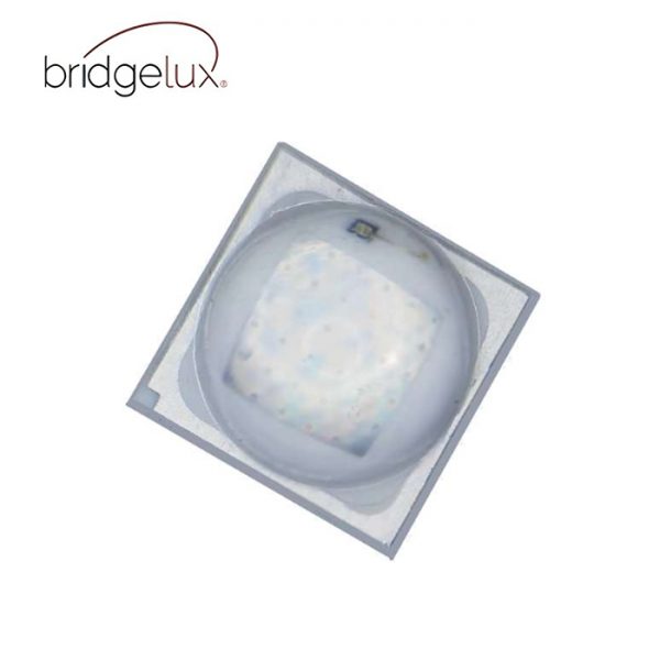
Bridgelux® SMD 3535 2W 3V
The Bridgelux SMD 3535 offers exceptional performance in a compact LED package. Hyper Blue with best value for highest PPE. Most compact high power LED with proven robustness, high reliability, long lifetime and low thermal resistance. It’s high PPE capability reduces the number of LEDs and enables industry leading system level lumen per dollar. The SMD 3535 is ideal as a drop in replacement for emitters with an industry standard 3.5mm x 3.5mm footprint.
Features
• Package: SMT ceramic package with silicone lens
• ESD 8kV HBM. JEDEC-JS-001-HBM and JE-DEC-JS-001-2012
• Typ. Radiation: 130° (Lambertian emitter)
• Radiant Flux :Typical 1500mW @700mA
• Photosynthetic Photon Efficacy
PPF_typical. 5.7 μmol/s @700mA
PPE_ typical. 2.8 μmol/J @700mA
Benefits
• Lower operating and manufacturing cost
• Ease of design and rapid go-to-market
• Compliant with environmental standards
• Design flexibility
• Horticultural Lighting applications

| Product Family | Product | Part Number | Data Sheet | Doc Number | Gen | CCT (K) | Current (mA) | Voltage (V) | Dominant Wavelength (nm) | Total Radiant Flux (mW) | Power (W) | PPF (µmol/s) | PPE (µmol/J) | Substrate Size (mm) |
|---|---|---|---|---|---|---|---|---|---|---|---|---|---|---|
| BXEX | 3535 1.5W 2V | BXEX-45B-11H-3HH-00-00-0 | Download Data Sheet | DS1720 | Blue | 700 | 2.9 | 452 | 1500 | 2 | 5.7 | 2.8 | 3.45×3.45×2.15 |
Table 1: Selection Guide, Pulsed Measurement Data at 700mA (Tj=Tsp=25°C)
| Part Number1,5 | Color | Nominal
Drive Current (mA) |
Forward Voltage3, 4
(V) |
Typical
Dominant Wavelength(nm) |
Typical
Peak Wavelength(nm) |
Typical
Pulsed Total Radiant Flux (mW) |
Typical
Power (W) |
Typical
PPF (umol/s) |
Typical
PPE (umol/J) |
||
| Min | Typical | Max | |||||||||
| BXEX-B45-11H-3HH-00-00-0 | Blue | 700 | 2.7 | 2.90 | 3.1 | 452 | 447 | 1500 | 2.0 | 5.7 | 2.8 |
Table 2: Performance at Commonly Used Drive Currents
| Part Number | Drive
Current1 (mA) |
Typical Vf
Tsp = 25°C (V) |
Typ Pulsed Total
Radiant Flux Tsp = 25°C (mW) |
Typical PPF
Tsp = 25°C (umol/s) |
Typical PPE
Tsp = 25°C (umol/J) |
| BXEX-B45-11H-3HH-00-00-0 | 50 | 2.62 | 116 | 0.44 | 3.34 |
| 100 | 2.66 | 232 | 0.87 | 3.28 | |
| 150 | 2.69 | 346 | 1.30 | 3.22 | |
| 200 | 2.71 | 457 | 1.72 | 3.17 | |
| 250 | 2.73 | 567 | 2.13 | 3.12 | |
| 300 | 2.75 | 676 | 2.54 | 3.08 | |
| 350 | 2.77 | 783 | 2.94 | 3.03 | |
| 400 | 2.79 | 886 | 3.33 | 2.99 | |
| 450 | 2.80 | 993 | 3.73 | 2.95 | |
| 500 | 2.82 | 1095 | 4.11 | 2.91 | |
| 550 | 2.84 | 1198 | 4.49 | 2.88 | |
| 600 | 2.85 | 1298 | 4.87 | 2.85 | |
| 650 | 2.87 | 1396 | 5.24 | 2.82 | |
| 700 | 2.90 | 1500 | 5.70 | 2.80 | |
| 750 | 2.91 | 1594 | 5.98 | 2.75 | |
| 800 | 2.92 | 1692 | 6.34 | 2.72 | |
| 850 | 2.93 | 1786 | 6.70 | 2.69 | |
| 900 | 2.94 | 1884 | 7.06 | 2.67 | |
| 950 | 2.95 | 1975 | 7.39 | 2.64 | |
| 1000 | 2.97 | 2069 | 7.74 | 2.61 | |
| 1050 | 2.98 | 2162 | 8.09 | 2.59 | |
| 1100 | 2.99 | 2252 | 8.43 | 2.56 | |
| 1149 | 3.01 | 2344 | 8.77 | 2.54 | |
| 1200 | 3.02 | 2430 | 9.09 | 2.51 | |
| 1250 | 3.03 | 2519 | 9.43 | 2.49 | |
| 1300 | 3.04 | 2608 | 9.76 | 2.47 | |
| 1350 | 3.05 | 2698 | 10.09 | 2.45 | |
| 1400 | 3.07 | 2781 | 10.40 | 2.42 |
Table 3: Electrical and Thermal Characteristics
| Part Number 1 | Drive Current
(mA) |
Forward Voltage
(V) 1,2 |
Typical
Temperature Coefficient of Forward Voltage △Vf/△T (mV/ºC) |
Typical
Thermal Resistance Junction to Solder Point3 Rj–sp (C/W) |
||
| Minimum | Typical | Maximum | ||||
| BXEX-B45-11H-3HH-00-00-0 | 700 | 2.7 | 2.9 | 3.1 | -1.3 | 3.0 |
Table 4: Maximum Ratings
| Parameter | Maximum Rating |
| LED Junction Temperature (Tj) | 150°C |
| Storage Temperature | -40°C to +105°C |
| Operating Solder Point Temperature (TSp) | -40°C to +105°C |
| Soldering Temperature | 260°C or lower for a maximum of 40 seconds |
| Maximum Drive Current | 1400mA |
| Maximum Reverse Voltage2 | – |
| Moisture Sensitivity Rating | MSL3 |
| Electrostatic Discharge | 8kV HBM. JEDEC-JS-001-HBM and JEDEC-JS-001-2012 |
Table 5: Total Radiant Flux Bin Definitions at 700mA, Tsp=25°C
| Bin Code | Minimum | Maximum | Unit | Condition |
| EU | 1300 | 1350 | mW | IF=700mA |
| FU | 1350 | 1400 | ||
| GU | 1400 | 1450 | ||
| HU | 1450 | 1500 | ||
| IU | 1500 | 1550 |
Table 6: Forward Voltage Bin Definition at 700mA, Tsp=25°C
| Bin Code | Minimum | Maximum | Unit | Condition |
| 8 | 2.6 | 2.7 | V | IF=700mA |
| 9 | 2.7 | 2.8 | ||
| A | 2.8 | 2.9 | ||
| B | 2.9 | 3.0 | ||
| C | 3.0 | 3.1 |
Table 7: Peak Wavelength Bin Definition at 700mA, Tsp=25°C
| Bin Code | Minimum | Maximum | Unit | Condition |
| B1 | 420 | 440 | nm | IF=700mA |
| B2 | 440 | 460 |


